Fixing the PCB
There was a small error in the PCB:
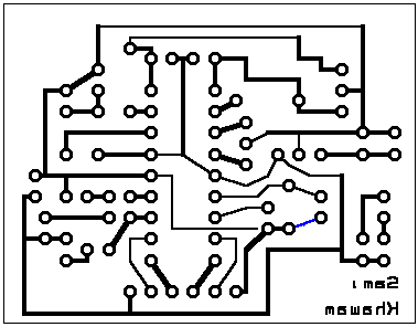
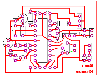
and the new ones are:
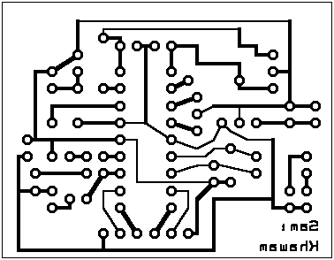
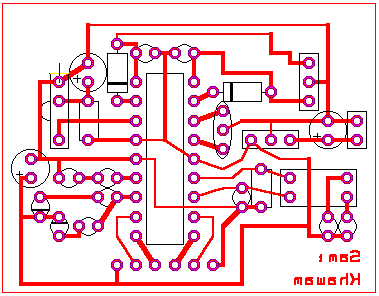
If you have already built the PCB, then it is very simple to fix this
error:
-
Cut the colored line (in the first 2 images). Use a screw driver of a cutter.
(Remember that this image is reversed!).
-
Check that it is not connducting more.
-
Solder DIL Switches.
-
Now put the resistor (R3 here):
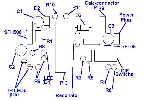
-
Leave some part of the pin going out, and solder the resistor.
-
Now push the rest of the pin to make it touch the pin of the DIL-Switch
( like the new connection)
-
Now solder it with the pin of the DIL-Switch.
I know my explanation is poor , I will soon include
a drawing describing this.
Back to index.
Author : Sami
Khawam
[Linking software] [ASM
archive]
[PICLink] [IR
Link]
[PIXpander]
[PIC16x84
programmer]
This page has been loaded times
since 18.1.98


