 Linking
software Linking
software
ASM
archive
PICLink
 IR
Link IR
Link
PIXpander
PIC16x84
programmer
Hosted by:

|
Infor
for Building the dld Kits
The components
placement on the PCB is:
Notes:
-
The two 680k and two 18k resistors
should be soldered before soldering the PIC socket, they go under it. Thanks
to Thomas Koglbauer for the
idea.
-
The left-most connection of
the 'calc connector' is the ground connection. ( On the old PCBs it was
the middle connection that went to ground).
-
The lower connection of the
'battery connector' is the ground one.
-
Some of kits recently bougth
contained a PCB slightly different from the one shown here. The SFH506
connection is different. If that's the case, the you should use:

The blue line is a wire that
should be put on the top part. The green wires should be down. They can
be solder. The parts placement is the same as the previous one.
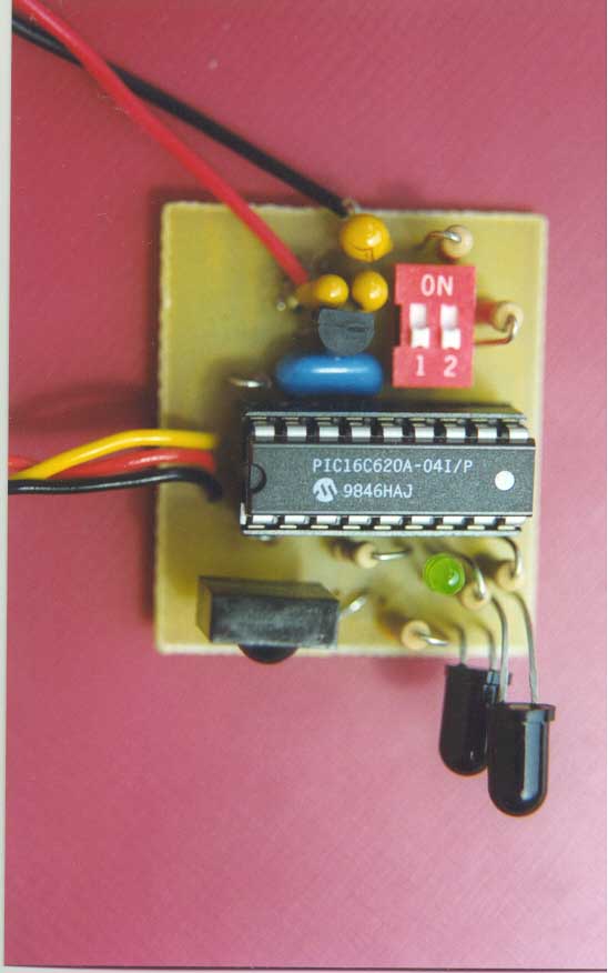
Photo of a built kit:
This is one built by me(note
that there are the 4 resistors under the PIC) :
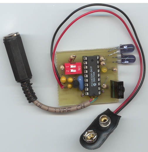
This is another photo of a kit
assembled by Scott Pierce . Note
also that there are the 4 resistors under the PIC. (This photo has been
fixed. The last one here had the LM2931 the wrong way).
Back
to index.
Author : Sami
Khawam |