|
Hardware
The
Circuit:
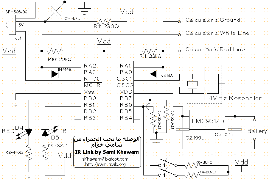
Notes on the schematics:
The resonator can be replaced
by an xtal with two 15pF to 33pF capacitorss.
The circuit can be powered from
a 9V battery, since there is a +5V voltage regulator. It can be also powered
from a 4.5V flat battery. A 4.5V battery has a long life and is cheap,
but a 9V one is more portable. Personally I prefer 4.5V batteries.
A PIC16C84 of a PIC16F84 can
be used. However a PIC16F84 is better and cheaper. When programming a PIC16F84,
make sure you set the fuses to: XT, WTD_ON and PWR_ON. You can also have
Pre-Programmed PICs from me.
Don't forget to download the
LITE code for the PIC from the Software downloads
section.
In the LITE version there is
only 1 switch on RB7. The other switch is only useful in the STANDART version.
R10 and R11 are new. They are
pull-up resistor that are needed on some calcs(some old calc versions does
have them built-in) and are also needed if the cable is long. On some calc
like the TI8x a value of 47k is enough. For the TI89 and TI92 22k are ok.
There was a previous schematic
that used a 78L05 regulator. You can find it here
. But the 2931Z5 regulator is
better
than the 78L05 because it takes
less power and gives more protection.
Parts:
The values of the components:
R1: 330 Ohm
R4,R6: 80 kOhm (or anything
near)
R3,R5: 620 kOhm (or anything
near)
R8: 470 Ohm
R9: 120 Ohm, this one depends
on the IR LED.
R10,R11: 22k Ohm.
C1: 4.7 uF. Tantalum electrolyte
is prefered.
C2: 100 uF if normal. If tantalum
are used then 22uF is enough.
C3: .1 uF. Tantalum electrolyte
is prefered.
Resonator: 4MHz
D1: IR LED, see text.
D2, D3: 1N4148
D4: Any RED LED.
SFH506: IR Reciever: SFH506-30
The
IR reciever module:
The essential part is the
SFH506-30 from Siemens. This one operates at 30khz.
It may be hard to find Siemens
parts in the US. Here
is a link to Siemens distributor
in the US:
http://w2.siemens.de/semiconductor/logistic/distrib/usdisti.htm
This module is compatible
with SFH505A also from Siemens (this one isn't more produced). Take a look
at the Datasheet
of the SFH506 to see the pins description.
I am also providing this
receiver. Check the Pre-Programmed PICs page.
The
IR LED:
Any IR LED that has a wavelength
of 950 nm can be used instead of the SFH415 from Siemens. In the Datasheet
of the SFH506-30 they say that with the SFH415 a range up to 34 m can be
obtained.
Extending
the range:
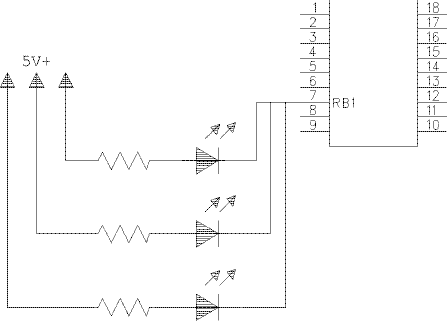
To extend the range, multiple
IR LEDs can be connected in parallel, the same way as D1 is connected.
Like this:
Resetting:
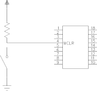
To reset the PIC you have
to unplug it from the calc and from the power, or you can add a simple
push button this way:
Using
a PCB:
Currently here are only 2
PCBs design. One by me and another by Thomas
Koglbauer . I
have also a PCB design that
I will release later.
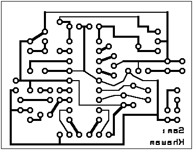
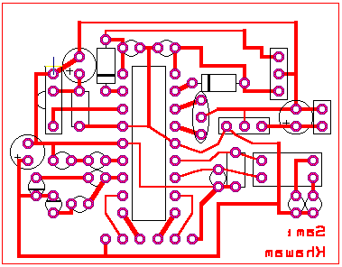
I have designed this PCB
for the IR Link. Some notes to it:
-
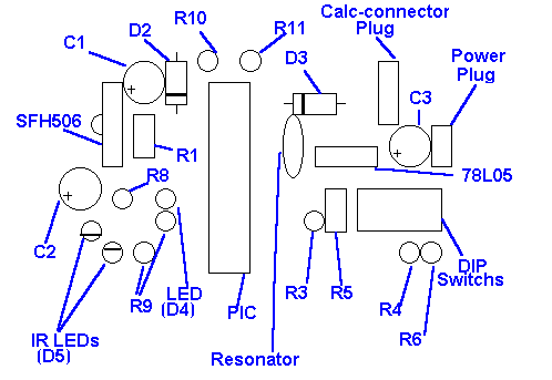
There is place for 2 IR LEDs
and their 2 resistors. You can use only one IR LED.
-
There are 3 connectors:
-
To the calc: With 3 pins.
-
To the battery: 2 pins.
-
To extra hardware: 6 pins: 4
for the I/O expansion and 2 for power.
-
Before printing the PCB you
have to scale and mirror the image!
I have tested it and it is working.
There was a tiny error in the old PCB that was on this page.
If you have built it, here
is how to fix the error: pcbfix.htm
The PCB:
The Tracks and components:
The components description:
Second
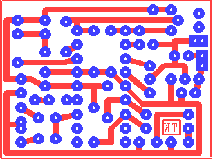
PCB design:
Thomas
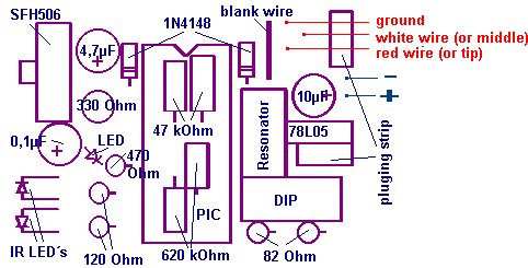
Koglbauer sent me this PCB desig, which is smaller than the one above:
 The parts placement:
Using
a strips-board:
A strips-board can be used
to make it easier to build the link. All you have to do is to cut some
strips and to solder the components. Antoine
Mercier has proposed the placement of the component. Thomas
Koglbauer sent me a correction and an unpdate of it. On the image
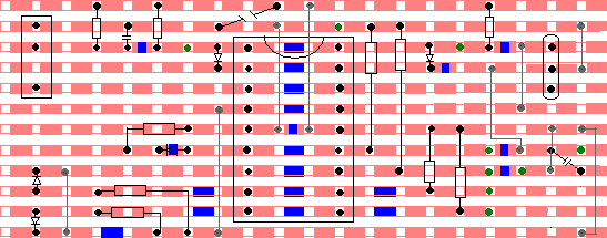
you have :
-
The tracks are in orange.
-
The breaks are in blue. Here
you have to cut the strip.
-
The places of the components
are in black. You have to solder them.
-
The green round is where you
have to solder the cables.
-
The gray connections are the
wires or metals that connects two strips.
-
The 0V isn't shown here. It
will be added soon.
See the first photo of my circuit
to get an image on how it will be done.
The places of the components:
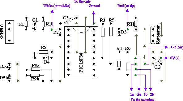
The front view:
Back to
index.
Author : Sami
Khawam |


